Cadence Design Automation
A live bridge between an AI agent and two licensed Cadence applications while they run — OrCAD Capture and Allegro PCB Editor. One MCP server holds a TCP connection into each, reading and writing their real in-memory design databases directly.
- Language
- Python
- Schematic tool
- OrCAD Capture 17.4
- PCB tool
- Allegro PCB Editor 17.4
- Transport
- TCP — Capture 9020, Allegro 9030
- Tools exposed
- 12, via MCP
- Offline tests
- 46
- Status
- Active
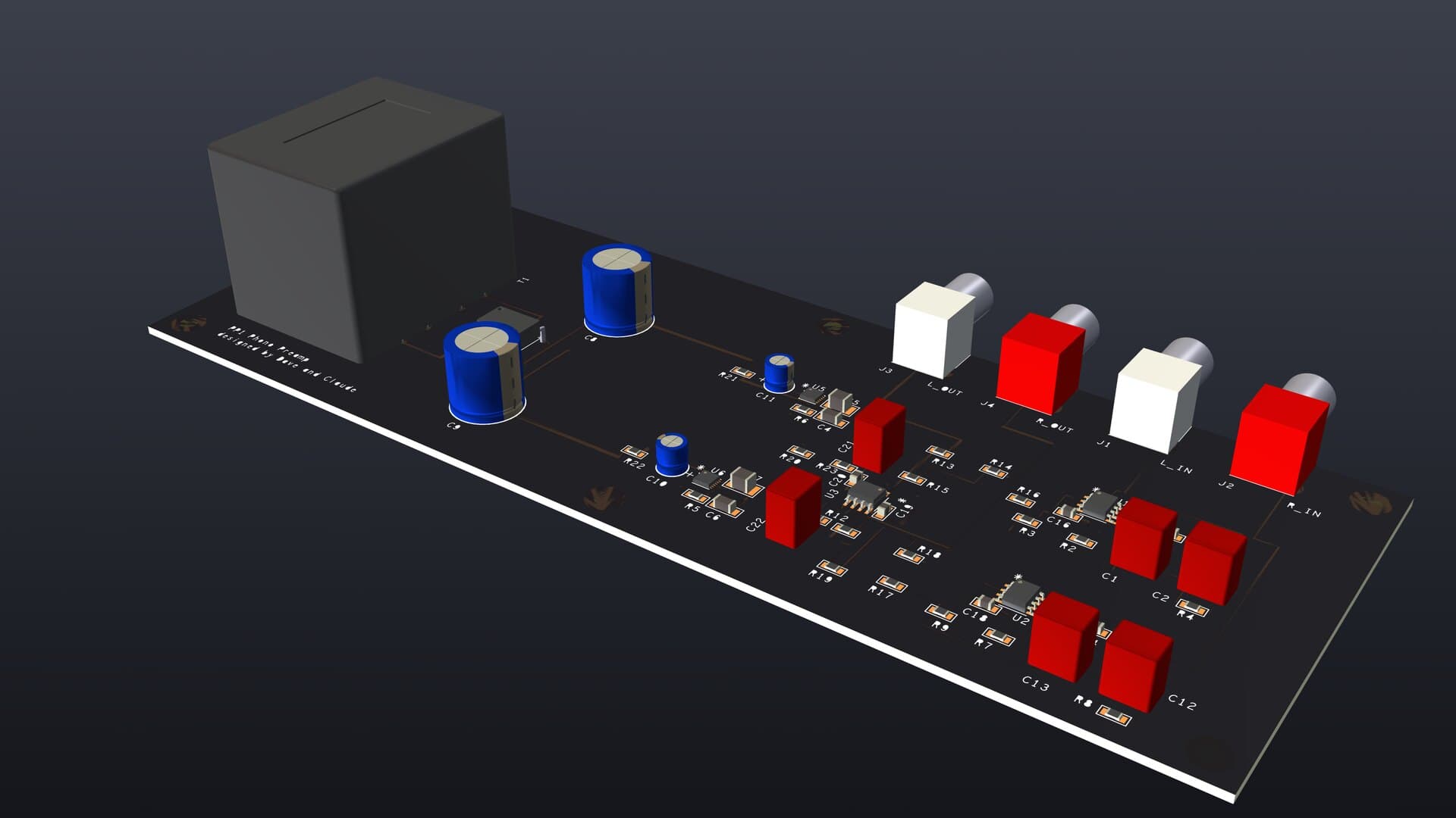
Fig. 1The assembled PP1 board. Rendered from the Allegro board database and the 3D models on its footprints — not photographed.
What it is
OrCAD Capture ships a TCP command server; Allegro's SKILL language has no socket support at all, only a way to spawn a child process wired to its own stdin and stdout. This project builds a bridge for each — a real client for Capture's server, and a small relay process that lets Allegro's SKILL interpreter talk to a socket by proxying through pipes — and puts one MCP server in front of both, so an agent sees twelve tools instead of two incompatible transports.
Everything it drives is real: property reads, part placement, wire creation from the database layer, arbitrary SKILL evaluation on the Allegro side. It was developed and is still tested against a real 57-part, two-page schematic — a moving-coil phono preamplifier — on a licensed 2019 Cadence installation.
What it does
- Capture bridge
A client for OrCAD Capture's TCL Communication Server — reads parts and connectivity, edits properties, places parts, and saves.
- Allegro bridge
A stdio-to-socket relay spawned by Allegro itself, since SKILL has no socket support — exposes structured board queries and arbitrary SKILL evaluation.
- MCP server
One server, twelve tools, fronting both bridges. Read-only by default; a --allow-write flag exposes property edits and saves.
- Board checkers
Placement (keepin, overlap, creepage, symmetry), dangling copper, silkscreen clutter, and routing isolated pins onto a plane — all driven from live Allegro state.
- Design data stays out
Net names, mounting holes, BOM — anything specific to one board — lives in a gitignored board.json, not in this repo. Checks refuse to run rather than silently pass when it's missing.
- Protocol tests
46 offline tests exercise the bridge protocol without needing Capture or Allegro running.
One server, two live database connections
The two bridges look symmetric from the MCP server's side, but they exist for different reasons underneath. Capture ships a TCP server, so the client just connects to it. SKILL has no socket support at all — its only inter-process primitive is ipcBeginProcess, which spawns a child wired to stdin and stdout. So on the Allegro side, the spawned child owns the actual socket, and SKILL talks to its own child process over pipes instead.
- Capture reads
- parts, connectivity, arbitrary TCL
- Capture writes
- properties, part placement, save
- Allegro reads / writes
- arbitrary SKILL evaluation
- Rollback
- Allegro only — Capture batches, no rollback
Unauthenticated by default, and that's disclosed, not discovered
Capture's command server binds every interface, not just loopback — 0.0.0.0:9020 and [::]:9020, measured, not assumed. Dispatch is unrestricted and there is no authentication anywhere in the path: any host that can reach that port can execute arbitrary code as whoever is running Capture. That's Cadence's own default, not something this project introduced.
A loopback-only starter script is included and used by default. Even bound to 127.0.0.1 it's still unauthenticated local RPC — any process on the machine can use it — a reasonable trust boundary for a design-automation channel on one workstation, but a deliberate choice to make, not a default to leave running on a shared or untrusted network.
Tested against a real board, not a mock
The tooling was developed against a real design instead of a synthetic one — a moving-coil phono preamplifier, 57 parts across two schematic pages, laid out on a four-layer, 8 by 3 inch board with split ground and power planes. The board's component-level details — BOM, exact routing, net names — are intentionally not published in the automation repository; they belong with the board, which is also why per-board configuration lives in a gitignored board.json rather than in the repo itself.
- Stackup
- 4 layers — signal / GND plane / PWR plane / signal
- Size
- 8.000 × 3.000 in (203.2 × 76.2 mm)
- Placements
- 57 — 40 SMT, 17 through-hole, all top side
- Finest pitch
- 0.5 mm DFN (LT3045 / LT3094)
- Finish
- ENIG
- Revision
- Board v1.8, fab package v1.9
The schematic it was built from, both pages. These are the source the bridge reads: the reference designators, values and node names visible here are the same ones the automation returns, and the same ones that end up in the simulation deck later on.
The renders below come from the same Allegro database — the 3D models on each footprint, the silkscreen, the solder mask, exactly as the fab package describes them. They are the closest look at the board available until real ones come back from the fab house.
A caught exception with a plausible default turned 3 errors into 89
A helper meant to read a part's reference designator returned "?" for every part for months — not because the parts were unannotated, but because it was called with one argument when the underlying API needed two. "?" looked exactly like a genuinely missing value, so nothing caught it. Three separate bugs shaped exactly like this one inflated one audit from 3 real errors to 89.
The fix wasn't a better catch block. It was refusing to let a caught exception produce a value that could be mistaken for real data — the same instinct behind board.json refusing to run an unconfigured check rather than reporting a silent pass.
The schematic the bridge read, simulated against the RIAA curve
Reading a design is only half of it. The bridge was used to pull the schematic's pin-level connectivity out of OrCAD Capture — 32 nets, 149 pin references — and that netlist was translated into a SPICE deck, simulated in LTspice, and parsed back with the raw-file parser from the companion LTspice project. Nothing in the chain was transcribed by hand: the deck generator refuses to emit a netlist if any node ends up with fewer than two connections, so a transcription slip becomes an assertion failure rather than a plausible wrong answer.
The circuit is a moving-coil phono preamplifier: 100 ohm input loading, an LT1028 first stage with an active RIAA feedback network, and an LM4562 output stage. Measured gain at 1 kHz is 63.7 dB.
As measured, the worst deviation was minus 1.78 dB at 20 Hz — much larger than anywhere else in the band, and three times worse than the design notes recorded. It is not the RIAA network. The interstage coupling capacitor forms a high-pass filter with the following stage's input resistance at 15.9 Hz. The product of those two sets the corner, so raising the resistor fixes it as well as raising the capacitor does, and both measure plus 0.19 dB at 20 Hz — but the resistor is a chip part that drops into the existing footprint, where a larger film capacitor would force a re-layout. The schematic now carries the larger resistors. Noise analysis puts the cost at 0.29 dB, of which 0.27 dB is the unavoidable price of opening the response down to 20 Hz at all.
The same setup answers a question the project had previously settled by reading a datasheet legend. The RIAA capacitors were once specified at 1 percent — a target that was never sourced and got written into the documentation as though it had been achieved — then corrected to a 10 percent part, then changed to a 5 percent one. What that choice actually costs was never measured until now.
Frequency response is only half the picture. The same netlist run in the time domain shows a quarter-millivolt cartridge signal arriving at the output as 418 millivolts with the waveform intact, and sweeping the input amplitude until the output stops tracking gives the overload margin — 31 dB above normal groove level before the first decibel of compression, with the output clipping on the supply rails at just under 15 volts, exactly where a plus or minus 15 volt supply says it should.
Those plots are drawn from LTspice's output, not by LTspice — the numbers are the simulator's, the rendering is a script's, which is what makes them legible. Here is the same result as the tool itself shows it. The deck behind it carries the schematic's own node names — L_STG1_FB, L_RIAA_MID, L_STG2_CPL — rather than invented ones, which is the actual join between these two projects: the simulator is reading the design, not a copy of it.
And the deck itself, which is the artefact the bridge actually produced. Every line of it was written from what the schematic returned — component values, node names, pin order — with the analysis directives appended. It is short enough to read, which is the point: this is the whole translation layer between a schematic database and a circuit simulator.
- Gain at 1 kHz
- 63.7 dB
- RIAA deviation, 100 Hz to 20 kHz
- within 0.35 dB
- RIAA network alone, 20 Hz to 20 kHz
- within 0.4 dB
- Worst case, 5 percent capacitors
- 0.73 dB at 20 kHz
- Worst case, 10 percent capacitors
- 1.14 dB at 20 kHz
- Monte Carlo trials
- 300 per tolerance class
- Overload margin over 0.3 mV
- 31.3 dB
- 1 dB compression
- 11.0 mV peak in, 14.9 V peak out
- Output noise, 20 Hz to 20 kHz
- 146 uV rms
- Input-referred noise
- 95.5 nV
What this does not cover is worth stating. The output stage uses a behavioural op-amp model because no vendor SPICE model ships with LTspice for that part, and the regulators are modelled as ideal rails rather than as the real low-noise parts on the board — so the supply rejection and the regulators' own noise contribution are both assumed away. The noise figures here come from the first stage's vendor model and the resistors around it, which is the dominant term for a moving-coil front end but not the whole of it. Distortion was not simulated at all. Those are the next things to measure, not things this already proves.
Go read the source
The bridge implementations, the MCP server, the board checkers, and the write-up of what actually breaks against a live 17.4 install are all in the repository.