TM4C123G LaunchPad DAQ
An EK-TM4C123GXL LaunchPad — a low-cost microcontroller dev board, not a custom analog instrument — sampling a 12-bit ADC via uDMA and streaming it over USB Full-Speed CDC to a PySide6 + PyQtGraph GUI. The project's core discipline shows up in its second half: a throughput investigation that measured, drew a conclusion, shipped a fix that changed nothing, and only found the real cause by measuring again instead of trusting the first diagnosis.
- Board
- EK-TM4C123GXL — TM4C123GH6PM, Cortex-M4F @ 80 MHz
- ADC
- 12-bit, ADC0 SS3 via uDMA ping-pong
- Link
- USB Full-Speed CDC — VID:PID 1CBE:0002 (J2)
- Sustained streaming
- 333 kS/s, zero loss (up from 200 kS/s)
- Burst capture
- Up to 8192 samples, edge-triggered, 5 rate presets verified
- Host GUI
- PySide6 + PyQtGraph, with an automated test harness
- Status
- Active
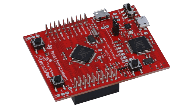
Fig. 1The actual board this project targets, exactly as it ships. Board photo: Texas Instruments, from the EK-TM4C123GXL product page (ti.com/tool/EK-TM4C123GXL).
What it is
A TM4C123GH6PM LaunchPad — a low-cost microcontroller dev board, not a custom analog instrument — samples ADC0 on PE3 through a uDMA ping-pong pair, an ISR drains the finished half into a 16 KB ring buffer, and the main loop drains that over a USB CDC link to a PySide6 GUI. The self-test signal is the board's own PWM, on PB6, jumpered straight to the ADC input — no external signal generator required.
The interesting work is on the USB side of that link, and it took two rounds to get right. The first fix — endpoint double-packet buffering — was aimed at what looked like the actual limit and changed nothing; only measuring the CPU itself found the real one, a per-byte interrupt-disable buried in TivaWare's own ring-buffer helper. Replacing it moved the safe continuous rate from 200 kS/s to 333 kS/s, and only then did the original diagnosis become true.
What it does
- ADC acquisition
12-bit ADC0 SS3 sampled via uDMA ping-pong, with the completion ISR draining finished halves into a ring buffer.
- Streaming mode
USB CDC delivers 333 kS/s continuously with zero loss, measured at the byte level — up from 200 kS/s before the transmit-path rewrite.
- Custom transmit ring
A private 4 KB ring, filled and drained by plain memcpy, replaces a call into usblib's USBBufferWrite that turned out to be the real bottleneck — and frees enough SRAM to make the swap free.
- Burst capture
Edge-triggered SRAM capture up to 8192 samples, with configurable level, rising/falling slope, pre-trigger percentage, and single/normal/auto arming — verified at all five ADC rate presets, landing within 0.004% of the target acquisition rate every time.
- Self-healing acquisition
A SysTick watchdog detects a stalled uDMA ping-pong (unchanged sample count for 100 ms) and rebuilds the channel in about a second, surviving an attached debugger halting the CPU.
- Dense wire protocol
Two 12-bit samples packed into 3 bytes, with 0xFF reserved as a status marker and no sync byte — the host re-derives alignment from the invariant that data triplets can never start with 0xFF.
- Host GUI
PySide6 + PyQtGraph, including burst controls, a frozen-frame display, and an automated test harness.
- Live display triggerNew
The streaming view holds still like a scope: each refresh finds the newest hysteretic level crossing in the ring and draws the window with t=0 on it, sharing level, slope and pre-trigger with the burst engine. Auto, Normal and Off, plus the space bar as Run/Stop. Host-side only — no firmware or protocol change.
A ring buffer on each side of the USB endpoint
ADC0 SS3, sampled by uDMA in a ping-pong pair, hits 400,687 S/s on command — getting there needs the ADC_INT_DMA_SS3 completion interrupt enabled and cleared, not the sequence-completion interrupt ADCSequenceDMAEnable implies, but once that's right the ADC keeps up with anything asked of it.
Finished samples land in a 16 KB ring buffer. From there the current design differs from the first one: main.c now keeps its own 4 KB transmit ring instead of calling into usblib's USBBufferWrite, filling and draining it with whole-packet memcpy calls. That rewrite is Section 04's subject — the fix for a bottleneck that first looked like the USB bus, and wasn't.
- ADC max (on command)
- 400,687 S/s
- Sustained streaming (zero loss)
- 333 kS/s = 501.5 kB/s
- Peak measured throughput
- ~516 kB/s — 42% of USB FS bulk ceiling
- Wire protocol
- 3 bytes / 2 samples (1.5 B/sample)
- Sample A saturates at
- 4079 (3.287 V) — 0xFF is reserved
- Firmware footprint
- ~20.5 KB flash, 27,593 / 32,768 B SRAM (5.1 KB free)
The LaunchPad in Fig. 1 ships with an on-board In-Circuit Debug Interface — TI's own name for J1 — stackable BoosterPack headers for plug-in expansion boards, and two 12-bit ADC modules, which TI's kit listing rates at 2 MSPS combined, 1 MSPS each. This project drives one of them, through one sequencer, at up to 400,687 S/s. The chip also carries 2 KB of EEPROM, untouched by this firmware. The roadmap's next hardware step — a second analog channel — has silicon already sitting on the board waiting for it.
The fix that changed nothing pointed at the fix that did
The first diagnosis was that usblib's class driver could only keep one 64-byte packet in flight per endpoint, capping the link regardless of what the hardware could do. Endpoint double-packet buffering (DPB) was the fix that diagnosis implied — verified set in hardware (TXFIFOSZ = 0x13) — and it made no measurable difference. That result was correct. The diagnosis behind it was not: the device was never waiting on the endpoint. It was burning CPU in the copy that fills it.
USBBufferWrite calls down into TivaWare's USBRingBufWrite, which copies a batch one byte at a time through UpdateIndexAtomic — a helper that globally disables and re-enables interrupts on every single byte. A 768-byte batch is 768 function calls and 768 CPSID/CPSIE pairs. Measured directly: **1,564 µs per call and 69.9% of the CPU**, against 17.4% for the entire USB interrupt handler combined. Double-packet buffering was never going to help a device that was CPU-bound before a sample ever reached the endpoint.
The fix was to stop calling USBBufferWrite at all. main.c keeps a private 4 KB transmit ring and hands the CDC class whole 64-byte packets directly, filling and draining both ends with memcpy. Only after that rewrite does the original diagnosis become true: the transmit ring now measures never empty (0%), and 94% of send attempts find the class still busy with the previous packet — the device is genuinely serialized on one packet in flight, for the first time. Double-packet buffering is the correct next step now, not the dead end it looked like the first time around.
- USBRingBufWrite cost
- 1,564 µs/call, 69.9% CPU
- Whole USB ISR, for comparison
- 17.4% CPU
- Zero-loss ceiling, before → after
- 200 kS/s → 333 kS/s
- Peak throughput, before → after
- ~358 kB/s (29%) → ~516 kB/s (42%)
- Free SRAM, before → after
- 1.1 KB → 5.1 KB
- Transmit ring occupancy (after)
- 0% empty; 94% of sends find class busy
If the link is the ceiling, don't stream through it
Burst capture fills SRAM at full ADC rate, with an edge trigger and a pre-trigger buffer, then drains the finished frame over the same USB link afterward, off the acquisition critical path — sidestepping the link's limit entirely, whatever that limit measures on a given day. Streaming and burst are mutually exclusive and share the same buffer; while burst is armed, the ADC ISR stops filling the ring and the streaming drain is skipped entirely (measured: zero stray samples).
Verified at all five ADC rate presets — 100 k, 200 k, 250 k, 333 k and 400 k S/s — each returning a complete 8192-sample frame with the trigger at exactly the requested offset. Checked against the acquired rate measured from the data itself, against the known PWM period: 100 k, 200 k, 250 k and 400 k land at +0.00%, and 333 k at 333,320 S/s (−0.004%). The top two rate presets exceed what the link can stream continuously — exactly the case burst capture exists for.
- Max frame length
- 8192 samples
- Pre-trigger (GUI presets)
- 0 / 25 / 50 / 75 %
- Slope
- Rising or falling
- Arm modes
- Single, Normal, Auto (200 ms re-arm)
- Verified rate presets
- 100k / 200k / 250k / 333k / 400k S/s
- Full 8192-sample frame
- 12,288 bytes, ~34 ms on the wire
A display trigger makes the stream hold still
Burst capture had a trigger from the start; the live view did not. It drew the last N samples of the ring on every refresh wherever the edges happened to fall, so a 10 kHz square wave at a 2000-sample window was a scrolling smear. The fix is the same thing every oscilloscope does: on each refresh, search the freshest few windows of the ring for the most recent level crossing in the chosen slope — with a small hysteresis band so noise cannot re-arm it — and draw the window aligned to that edge, pre-trigger fraction to its left.
It reuses the level, slope and pre-trigger controls the burst engine already had, so one setting drives both, and it switches the x-axis to milliseconds with t=0 on the edge to match the burst frame. The search is vectorised numpy: a 500 k-sample window costs under 25 ms, a normal one tens of microseconds. Nothing in the firmware or the protocol changed. The space bar is Run/Stop, with the ring still filling underneath so that releasing shows the present rather than the past.
The only test source on the bench is the board's own PWM, a fixed square wave. For the clip, a debugger script rewrites that PWM generator's compare and period registers about 150 times a second over the ICDI port while the firmware runs — the Cortex-M debug port reads and writes memory without halting the core, and the PWM counter was confirmed still running between accesses. Duty sines, triangles, sawtooths, a random walk and a five-octave log chirp, with zero firmware changes. Verified in the data stream before it went on screen: duty swung 10 % to 87 % at exactly 0.5 Hz, and the chirp swept 1.7 kHz to 30 kHz at 0.25 Hz.
A halted CPU strands the uDMA, and a stray status byte shifts every sample after it
Attaching a debugger halts the CPU and strands the uDMA ping-pong with both halves STOPped — without a watchdog, the board streams nothing until it's reset. The SysTick watchdog now detects the stall (g_ui32SampleCount not advancing for 100 ms) and rebuilds the channel, so an ICDI read self-heals in about a second instead of requiring a power cycle.
The transmit ring has its own producer/consumer discipline to get right: ControlHandler runs in USB interrupt context, and the main loop is the ring's only producer. A flush landing between the producer's memcpy and its head update puts the stale head back, and the device then transmits kilobytes of stale bytes — which, with no sync marker in the protocol, the host never recovers from. Free space must also be re-read after servicing the status queue, since those writes share the same ring; sizing a batch from a figure taken before them overruns it by up to a full status queue.
The host-to-device command byte was originally matched against 0x60, ignoring bit 7 — which aliases the new 0xC0 burst/trigger code onto 0x40, the duty-cycle code. A trigger-level command would have silently changed the PWM duty cycle instead. The mask is now 0xE0.
Go read the source
The firmware, the wire protocol and burst/trigger state machine, the throughput investigation, and the PySide6 GUI with its automated test harness are all in the repository.